
Browse Items (970 total)
Sort by:
-
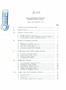
"Aero-Astrodynamics Laboratory bimonthly progress report : August and September 1967."
Includes: Projects Office; Advanced Studies Office; Aerospace Environment Division; Astrodynamics and Guidance Theory Division; Aerophysics Division; Dynamics and Fight Mechanics Division; Flight Test Division. -
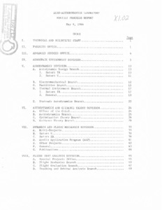
"Aero-Astrodynamics Laboratory monthly progress report : May, 1966."
Monthly progress report for May, 1966. -
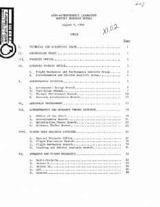
"Aero-Astrodynamics Laboratory monthly progress report : August, 1966."
Monthly progress report for August, 1966. -
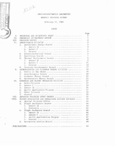
"Aero-Astrodynamics Laboratory monthly progress report : February, 1966."
Monthly progress report for Febuary, 1966. -
"Aero-Astrodynamics Laboratory monthly progress report : July, 1966."
Monthly progress report for July, 1966. -
"Aero-Astrodynamics Laboratory monthly progress report : June, 1966."
Monthly progress report for June, 1966. -
"Aero-Astrodynamics Laboratory monthly progress report : September, 1966."
Monthly progress report for September, 1966. -
"Aero-Astrodynamics Laboratory monthly progress report : January 12, 1966."
Monthly progress report for January 12, 1966. -
"Aero-Astrodynamics Laboratory monthly progress report : April 7, 1966."
"Monthly progress report : April 7, 1966." -
"Aero-Astrodynamics Laboratory monthly progress report : March 8, 1966."
"Monthly progress report : March 8, 1966." -
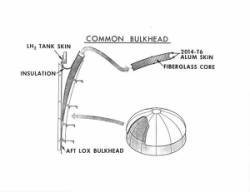
"Common bulkhead drawing."
8 x 10 inch black and white photograph; This is a cutaway drawing of the bulkhead with information about the LH2 tank skin, insulation, Aft LOX bulkhead, 2014-T6 alum skin and fiberglass core. Part of an envelope with photos accompanying C. E. Cataldo paper "Materials in Space Exploration." -
"A comparison of four control systems proposed for Saturn V launch vehicles."
Presented are the results of a study comparing four proposed control systems for the first stage flight of Saturn V launch vehicles. The primary basis of comparison is the effect on structural loads, using the bending moments at three stations as load indicators. Two of the systems sense only the vehicle attitude and attitude rate, while the other two systems also sense the lateral acceleration. A yaw plane wind response analysis, including rigid body translation, rigid body rotation, four bending modes, five slosh modes, and a non ideal control system, was performed. The winds used in the study were the Marshall synthetic profile and three selected Jimsphere-measured real wind profiles. Load relief obtained from the addition of accelerometer feedback in the control loop amounted to about 10 percent at maximum bending moment station. In view of predicted structural capabilities of the vehicle, this reduction in loads was not considered sufficient to offset the added complexity and the slight reduction in rigid body stability . -
"Interface Control Document Definition of Saturn SA-507 Flight Sequence Program."
The purpose of this document is to define the flight sequence events, time bases, stage switch selector channel assignments, LVDA Discrete Outputs, Inputs and Interrupts for the Saturn SA-507 & Subs vehicles. Special requirements and restrictions defined in this document will be imposed on the Marshall Space Flight Center and its contractors as applicable, to insure the proper functioning of the equipment in the various stages for required vehicle timing and sequencing to occur as outlined in this Interface Control Document (ICD). -
"IU/S-IVB Forward Skirt Orbital and Translunar Thermal Analyses."
This report determines the maximum and minimum solar and terrestrial thermal energy incident and absorbed by Saturn IB/V vehicles in earth orbit and translunar travel. The influence' of this external energy on the Instrument Unit Thermal Conditioning System performance, and consequently its adequacy to maintain the electronic packages at acceptable temperature limits is ascertained. Conclusions are: a) Methanol/water coolant temperature will deviate from 111 specifications only during translunar cold flights. However, adequate thermal conditioning of the electronic equipment would still be maintained. b) Instrument Unit missions exceeding 6 1/2 hours, or electronic packages heat dissipation magnitudes lower than 3 kw or higher than 8.5 kw, should be reviewed to ascertain thermal compatibility. -
"MSFC systems engineering capabilities (abstracts of reports)."
List of proposals, plans and other sections with subsections that describe studies or projects under that criteria. -
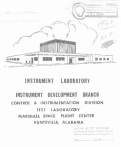
"Mission and facilities of Instrument Development Branch."
Describes the purpose and goes of the George C. Marshall Space Flight Center. Instrumental development branch. -
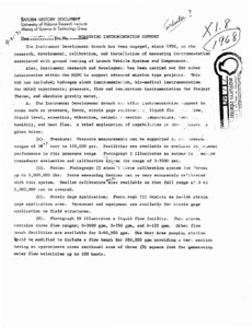
"Measuring instrumentation support."
Article refers to photographs, providing context to what is shown in them with formulas and measurements. -
"Saturn V service arms : preliminary engineering report."
This report presents the manufacturing requirements for fabricating Saturn V service arms and contains design and operating details of the service arms and associated equipment. Part 1 defines the areas of responsibility necessary for the manufacture of Saturn V service arms and associated equipment. Capability requirements, manufacturing processes, special techniques, schedules, and other areas are detailed in Part 1. The manufacturer selected to fabricate the arms and related equipment must meet the requirements (stated in Part 1. Part 2 contains design and operation details of the service arms, Command Module Access Arm, and related equipment used on or in support of the Launcher-Umbilical Tower for the Saturn V Vehicle at Complex 39. The design and construction of all basic arms is similar. Eight service arms are being designed. The arms are being designed to support all umbilical lines necessary to service the various stages of all Saturn V Vehicles. The arms are also being designed to allow personnel access to the vehicle. Some of the arms must be retracted before vehicle lift-off and others will retract following lift-off. This requirement necessitated the design of umbilical disconnect and arm retract devices which would ensure clearance between the arms and vehicle during lift-off. The Command Module Access Arm is a separate design concept. The arm is used only for astronaut access to the Command Module. Part 2 presents the preliminary design directed toward meeting the requirements stated above. -
"Michoud and Mississippi test operations : May 1965."
This document contains copies of management charts and photographs maintained in the Management Information Office of the Executive Staff on Michoud and Mississippi Test Operations. Information on other MSFC activities and facilities will be published in separate volumes as indicated on the following page. Most of these charges are included in Dr. von Braun's, Dr. Rees' and Mr. Gorman's Management Information Consoles. -
Visual aids library slide guide.
This document includes revisions. There are missing pages from page 237-238. This reference document catalogues all MSFC oriented visual aids filed in the Visual Aids Library of Marshall Space Flight Center. These visual aids are updated by the Graphic Engineering & Models Branch, Industrial Operations Program Management Information Office, and the Research and Development Operations Management Office. The purpose of the Visual Aids Library is to provide management data visuals in the form of slides (3 X 4 and 2 X 2), or black and white prints, to MSFC offices and laboratories, and other centers, who have a valid requirement. The visual aids are issued on a loan basis in order to obtain as wide a use for each visual and to assure that the latest revisions are incorporated in the issued item. Visuals may be ordered from the Visual Aids Library, located on the 10th floor of building 4200 (Phone 876-7237, 876-6960, 876-0983). In addition to the visuals published in this book, photographs from prime contractors are available from Industrial Operations, Program Management Information Office, Room 621, building 4201. Visuals with erroneous or obsolete information should be brought to the attention of the Visual Aids Library, preferably in writing, so that corrections can be made immediately. This publication will be kept current through distribution of pages of new visuals and notification will be made on obsolete visuals so they may be crossed out in the catalogue. Comments and suggestions concerning this publication will be greatly appreciated. Changes in the distribution lists should be directed to Mr. Gordon 0. Willhite, or Mrs. Opal Tabor, Visual Aids Library, MS-G.